
Fulton Center, NYC
The Fulton Center is a $1.4 billion subway interchange in New York, that improves connections between six subway stations in Lower Manhattan and has regenerated an area badly affected by the 9/11 attack in 2001 and the economic crisis of 2008. With Arup as lead consultant, the project combined a wide range of engineering skills, from modelling pedestrian movements to underground work in difficult ground and managing the project through a succession of stops and starts caused by uncertain funding. The Fulton Center opened in November 2014, and was announced in October 2015 as the winner of this year’s British Construction Industry International Award.
The principal purpose of the Fulton Center project was to join up six stations on 11 separate lines that were expressly built by competing private railway companies (1902–1933) so that they would not join up. Constructed in the early 20th century, the entrances were narrow; passengers changing platforms had to use cramped passages, or rise to ground level and cross busy streets. Peak hour ‘dwell times’ for trains had become unacceptably high, reducing train frequency and increasing congestion still further, and the system-wide knock-on effects could affect services all day.
A key to the solution was a new central interchange building, the Fulton Center, on a site facing Broadway, through which most of the 300,000 passengers using the stations each day could be routed. This facility was designed in conjunction with three architects: UK firm Grimshaw Architects; the preservation architect Page Cowley; and, HDR/Daniel Frankfurt. The Center was required to be much more than a functional transport interchange with retail space above. New York needed an exciting, welcoming gateway building to Lower Manhattan that would symbolise and catalyse the area’s regeneration. The result is a simple three-storey steel and glass pavilion, surrounding a giant eight-storey dome structure capped with a 53ft-diameter oculus, inclined to draw the maximum amount of sunlight down through the building to the lowest subterranean level. It is lined with a large-scale installation, the Sky Reflector-Net, which involved a detailed collaboration between engineering, art and architecture.
However, it was underground that the real engineering challenges lay. Some 30 m below ground was sound bedrock, too deep and too difficult to reach by piling. Near the surface was a typical mixture of urban fill. In between, where almost all the work was to take place, was a treacherous mixture of sands and silts including Manhattan’s notorious ‘Bull’s Liver’ soil, a vibration-sensitive stratified silt and fine sand. This is prone to consolidation, causing settlement under construction vibrations, and rapidly loses strength when disturbed or wetted: in its saturated state, it can quake like jelly when shaken, and even flow like a liquid.
Project plan
A lot of the construction work for the project ran the risk of disturbing the existing tunnels and stations, most of which had been constructed by ‘cut-and-cover’ and all of which were ‘floating’ in the sands and silts, including the Bull’s Liver. At the start of the project, temporary station closures had been planned, but this was ruled out because of the transport disruption it would have caused. So, all the work had to be carried out around a live railway operating 24 hours a day, with 300,000 passengers passing through each day, and with just occasional weekend closures.

How the new Fulton Center interconnects six subway stations on 11 lines. Running north-south is the oldest and busiest route, the 4 and 5 Lines, built in 1902, which separates the new Dey Street concourse from the new Transit Center building with the Corbin Building in front. Running east-west is the newest and deepest, the A and C Lines constructed as cast iron tubes in 1933, with a large cut-and-cover mezzanine above © Arup
On top of this, the team had very little space at ground level beyond the confines of the Fulton Center site itself, and no full street closures were permitted.
The first challenge was the station with the A and C tube lines beneath Fulton Street which had been constructed in the 1930s in an unusual way. First, the two running tunnels had been driven, under compressed air just below the ground water level, and lined with cast-iron segments; then the space between had been opened up to form the platforms; and finally a long mezzanine area had been built over the top by cut-and-cover, for pedestrian ramps and corridors. The mezzanine needed to be rebuilt to accommodate new lifts and escalators, with an original line of columns down the centre removed and a new steel A-frame roof installed to transfer loads to the side columns.
The greatest concern was the effect all this work and the change of loading would have on the running tunnels beneath: if the cast-iron lining cracked, water would come in and the tunnel could flood. Arup used the old as-built records, as well as taking cores of the original cast-iron lining for laboratory testing and analysis, and combined this with its knowledge of the behaviour of cast-iron linings of a similar vintage in London tube tunnels. This was done to assess the ductility of the iron and the structural integrity of the tunnels and, in particular, to determine the maximum deflection that could be tolerated in the lining: fortunately, the iron proved less brittle than anticipated.
The greatest concern was the effect all this work and the change of loading would have on the running tunnels beneath
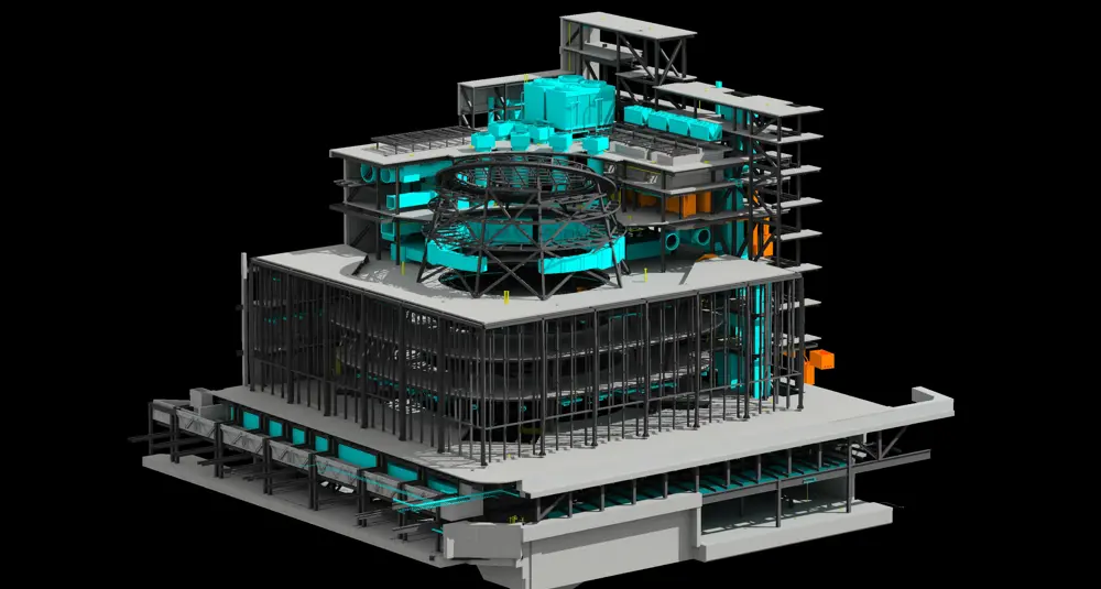
A 3D CAD/ BIM model used by different construction disciplines to look at the mechanical, electrical, structural, civil and plumbing elements of the Center. The model was uploaded into Bentley augmented reality software and then used by engineers onsite with iPads to compare site conditions with ‘as-built design records’ © Arup
Here, as elsewhere on the project, potential movement was modelled and parts of the stations and tunnels were fitted with deflection monitoring equipment. Sometimes and in some places, the tunnel tubes were tending to sink, at other times to float upwards. Phasing of the work proved critical, not just to control deflection in the tunnel, but to cope at all times with pedestrians using the stations and mezzanine, and traffic using Fulton Street overhead.
The new Fulton Center ‘floats’ on a concrete box, built with secant (interlocking) pile walls and a 1.7 m-thick raft laid directly on the carefully prepared sands and silts. The walls were propped temporarily by heavy steel struts and permanently by the diaphragm effect of the Fulton Centre’s concrete floors. A similar technique was used for creating the new, wide passenger concourse underneath Dey Street – see subway schematic.
The trickiest part was connecting the two, by opening up the area under the 4/5 Line station as a passage. First, come 120 steel mini-piles were sunk between the tracks during weekend possessions. Jet-grouting was used to create two cut-off walls directly under the station, forcing the side walls of the new passageway. Then the soil could be excavated beneath the station, and the exposed mini-piles replaced with permanent columns. Meanwhile train speeds on the Subway were restricted, to reduce vibration but also to reduce the large horizontal forces caused by sharp breaking.
It was early in one of these weekend possessions that a serious loss of ground was detected around one of the mini-piles as it was being placed- so serious that the subway operator had to be informed that the work would not be complete for hand-over and train operations at 5:00 am the following Monday. Resources were brought in from other sites and by concerted efforts, the hand-over was only delayed by half an hour, the biggest impact of any event during the project.

Looking across Broadway at the narrow west elevation of the Corbin Building, and the dome with its inclined oculus and skylight under construction to the north © Arup
Classic building rescued
Along the south side of the Fulton Center stands the Corbin Building, which was scheduled for demolition at the start of the project. The narrow eight-storey building, wedge-shaped in plan built in the 1880s was dull grey from a century and more of grime, its distinctive pepper-pot roofs long gone and its façade littered with iron fire escapes and with air conditioning units hanging from windows. The architect was Francis Hatch Kimball, described by contemporaries as ‘the father of the skyscraper’. Although modest by modern standards, at the time of its construction in 1888-9 this was (briefly) Manhattan’s tallest building. Kimball was a pioneer in the use of ironwork and terracotta, both materials used structurally and ornamentally, in realising his often extravagant designs. Research revealed a historical gem, and the building has been painstakingly restored and integrated into the Center – a task requiring the skills of the engineers as much as the conservation architects.
Two problems for the conversion both stemmed from the narrowness of the building: how to provide lateral stability, particularly to satisfy earthquake and wind-loading codes not mandated in the 19th century; and how to include building services, including lifts and fire-escape stairs, without reducing the usable floor space still further. Both were addressed by tying the structure into the Fulton Center and dome to the north via an ‘interstitial’ building - a new eight-storey steel frame against the ‘blind’ north wall of the Corbin Building, housing the new services and lifts.
But this only partly solved the structural problem. Analysis showed that the many new openings in the north wall created stress concentrations in the masonry walls, particularly just above street level. The solution was to encase the walls between level 2 and street level in a 100 mm-thick shotcrete layer on each face, heavily reinforced to provide ductility and anchored to the masonry by resin-dowelling several thousand L-shaped reinforcing bars.
Also it was difficult to provide lateral stability for the upper stories, since the Fulton Center itself had limited stiffness above level 3. The remedy was to introduce a concrete moment-frame into the upper levels, near the narrow western end of the building, to transfer the lateral loads down the building.
it was difficult to provide lateral stability for the upper stories, since the Fulton Center itself had limited stiffness above level 3
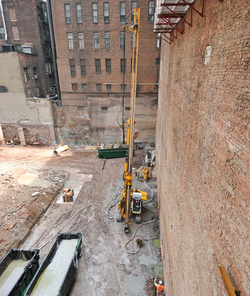
A jet-grouting rig stabilising the moving ground beneath the ‘blind’ north wall of the Corbin Building (on the right), to allow excavation to proceed below the building’s foundations © Arup
However the most challenging aspect of the whole renovation was the work below ground, which included sinking a new escalator shaft running along much of the length of the narrow building, from ground level to the lowest level of the new Center some 12 m below – and 6 m below the Corbin building’s existing foundations – through notoriously difficult ground.
This presented a challenge to support the eight-storey building during and after construction, and required the whole of the building to be underpinned. To counteract potential issues with the liquefiable soils, sections of the perimeter of the underpinning zone had first to be stabilised by a system of contiguous jet-grouting. Then the remaining sections under the walls were underpinned with mass concrete, using the traditional method of hand-digging and filling a series of narrow shafts no more than 900 mm wide, a task which in itself took more than a year.
Then the soils beneath the Corbin Building could be removed to create the escalator pit. The problem here, was transferring the large below-ground horizontal loads between the retaining wall to the south and the new floors of the Fulton Center. The solution involved a massive ring beam within Corbin’s escalator wellway.
Throughout these critical underground operations, the building was fitted with deflection monitoring equipment, the readings linked via software to hand-held devices so that engineers on site could get instant warning of any untoward movement, with a 6 mm shift sufficient to trigger an alarm. Total vertical movement of the south wall was a little over 50 mm, and half that for the north wall.
Massmotion
🚶 The software to model people’s movement
The Arup software MassMotion, though borrowing existing 3D models, has developed a completely new set of tools based on individual, virtual 'agents' in order to represent and understand people movement. These agents could be programmed to mimic human behaviour, for example pausing at a café for a cup of coffee or stopping at a travel information board, passing through a turnstile or going up an escalator, based on destination preferences. They make their own choices about appropriate actions based on the dynamics of their environment. The agents were assigned attributes based on field surveys: for example, the ratio of men to women (who, on average, walk at a slightly shorter step and slower pace than men), and whether they are commuters (who know where they are going) or tourists (who are not so sure).
Information from the architectural design was used to develop a virtual environment based on a set of polygon mesh objects that represent the walkable areas and obstructions within them. The walkable areas are then further broken down into circulation spaces, such as rooms, pavements or platforms and connection elements, including doors, stairs and passageways. The agents themselves will then decide their most appropriate routes across the environment between the various origins and destinations, their decisions based not just on distance, congestion and vertical movement but also on each agent's individual personality profile. Some agents will walk slowly and always wait to queue for the escalators; others will take the stairs at the first sign of congestion - and everything in between.
Agent profiles were based on existing data on pedestrian behaviour, combined with real counts of passengers at the existing stations. For calibration, the model was first applied to the existing layout, and the weighting factors were tweaked to get a better fit with survey results, and a 20% increase was factored in to represent growth during the construction period.
Since the Fulton Center, MassMotion has been further developed by Arup's software house Oasys for a variety of other applications including mass evacuation of buildings, managing major venues and designing buildings, sports stadia and retail spaces.
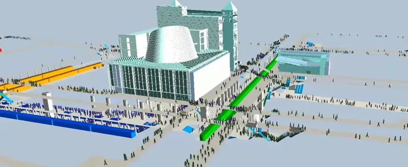
Fulton Centre- looking south. Analysing pedestrian movement in Lower Manhattan. The Centre is seen in pale green-blue with the World Trade Centre site to the right of the image. The green, blue and yellow blocks represent subway trains stopped at the station.
People movement
Planning the movement of people through the Fulton Center, with its network of passages, stairs, escalators and lifts, was particularly challenging. It was not just a question of predicting movements after opening day, passengers also had to be accommodated throughout the 10-year construction, so hundreds of combinations had to be tested, including contingency plans for each. If, for example, during a phase of construction, certain exits were closed and passageways restricted in width, could people still be safely evacuated from the platforms in an emergency? Arup could find no software that would do the job adequately, and so designed their own – see Massmotion. This software was also used during the COVID-19 pandemic to model social distancing.
The model not only provided graphical representation of where, for example, pinch points were causing congestion, but also allowed the design team to observe the real- time behaviour in realistic 3D as the agents passed through the Center, replicating the random and chaotic behaviour of humans better than previous systems were able to do. Movements were tracked of more than 48,000 people passing through the Center at any one moment. Now, designers were able to see how people would use their facility before it was actually built.
The model proved invaluable in planning the complex construction phasing of the project. After opening the Center, the most noticeable discrepancy between the model and reality was caused by an unpredicted change in land use of the area from offices towards housing: a higher proportion of local residents compared with incoming commuters meant, in particular, that more ticket machines were needed. Nevertheless the modelling helped the project succeed in greatly reducing congestion points: the station 'dwell times' for trains on the busy 4/5 Line were reduced down to about 20 seconds in peak times - to the delight of the Subway's operator.
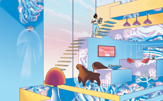
Sky reflector-net
🎨 The design and art competition create the unusual Fulton Center dome
As a result of a public art competition, US light artist and designer John Carpenter was appointed as a collaborative artist for an unusual art installation: an interdependent reflective lining, offset from the interior of the Fulton Center’s dome, to direct sunlight down from the sloping, circular oculus at the top. The final design involved a steel cable-net structure supporting nearly 1,000 coated aluminium infill panels using flexible, universal node connection assemblies.
The cable net is suspended from 56 connection points round the compression ring of the oculus, and anchored to beams at the bottom. The 3.2 mm-thick aluminium panels are heavily perforated, not just to reduce weight but also to permit interior air currents to pass through and to control the quantity of light reflected. They are linked by cruciform connectors attached to each corner and fixed to the cable’s nodes by swaging – cold-forming to provide a firm connection.
The artwork was visualised as a dynamic structure, able to respond to forces varying over time. This meant ensuring that the structure was sufficiently flexible, and checking that its movement would be contained within prescribed limits. A key to the former was the design of the cruciform connectors, to ensure that any movements did not transfer forces into the delicate aluminium infill panels. This was achieved by providing a single, fixed connection at the top of each panel, and oversized holes at the sides and bottom to allow for the maximum amount of movement as well as for construction tolerances.
A full-scale mock-up of 13 panels was built to test the system’s performance and to validate the construction procedure. The complete net was fabricated and assembled, together with all the node connectors, in a town in Massachusetts, test-lifted by a crane in a field outside the assembly facility, and then rolled up and delivered to the Fulton Center. There it was hoisted up and fixed to the oculus, and the infill panels inserted via suspended platforms and ‘cherry pickers’ over a period of about three weeks.
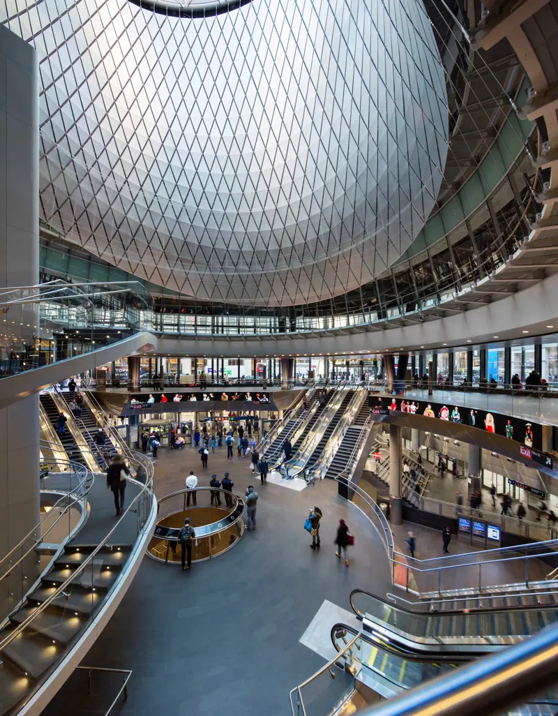
The new Fulton Center features open direct paths, widened corridors, and new mezzanines to separate entering, exiting, and transferring customers. The Sky Reflector-Net helps to draw light down from the inclined circular oculus deep into the subterranean levels of the Center, greatly reducing the costs of artificial lighting © James Ewing
Lessons learned
A key lesson from the project was that, for all the technical challenges that were identified and resolved, the most difficult task of all on a major project such as the Fulton Center was negotiating the mix of political, administrative and financial obstacles. Funding was drawn from federal, state and city funds, each with its own political agendas and different political tenures.
Not only the client – MTA Capital Construction – but other bodies including the operator (New York City Transit) and the Federal Transit Administration had to be satisfied. Differing requirements by different bodies required complex design code reconciliation. As Craig Covil, the Project Dorector, says: “Sometimes it was necessary to identify which were really ‘requirements’ and which were just ‘desirements’”. Frequent funding delays, including a six-month shut-down in 2005, required regular rescheduling. When Arup was appointed in 2003, completion of the project was targeted for 2009. The project was repackaged in 2007 with a revised opening date for the end of 2014, which was met.
Its design and engineering achievements have been recognised worldwide and in October 2015 the British Construction Industry awarded the Fulton Center project its International Award
The newly renovated Fulton Center now processes 300,000 daily passengers between 11 train lines. The improved Center not only simplifies transit connections, but provides 65,000 square feet of retail and office space. Its design and engineering achievements have been recognised worldwide and in October 2015 the British Construction Industry awarded the Fulton Center project its International Award. Then, in November the project received its 20th award to date – a winner at the World Architecture Festival in Singapore.
Throughout the critical underground operations, the building was fitted with deflection monitoring equipment, the readings linked via software to hand-held devices so that engineers on site could get instant warning of any untoward movement, with a 6 mm shift sufficient to trigger an alarm.
🖱️ For more information on the project, visit Arup's website.
***
This article has been adapted from "The Fulton Center, NYC", which originally appeared in the print edition of Ingenia 65 (December 2015).
Contributors
Hugh Ferguson
Author
Craig Covil was an engineer and Principal of Arup based in the firm’s New York office at the time of publication. He obtained a BSc Eng Hons from the University of Surrey and an MSc from Imperial College London. He worked on the Fulton Center from its start in 2003, and was Project Director from 2008. Craig led a multidisciplinary team of engineers, architects, planners and scientists in the delivery of this mega-project.
Get a free monthly dose of engineering innovation in your inbox
SubscribeRelated content
Civil & structural

Building the Shard
The Shard is one of London's most iconic buildings. The tallest in Western Europe, it was designed by Italian architect Renzo Piano and dominates the city’s skyline. Ingenia spoke to John Parker, project director for structural engineers WSP, who outlined the engineering decisions made in building the enormous steel and glass structure.

The return of arched bridges
Arch bridges are strong, durable and require little maintenance. However, very few had been built since the early 1900s until the FlexiArch was developed and launched in 2007. Now, there has been a minor renaissance for this ancient form of construction.

Creating user-friendly buildings
For Michelle McDowell, a former Business Woman of the Year, a passion for joined-up design thinking and building information modelling with a user-friendly approach has enabled her to pioneer revolutionary changes in her field.

Troja Bridge
In November 2014, one of the world’s largest network arch bridges was officially opened in Prague. The UK may soon have its first network arch bridge if the go-ahead is given for a new rail project in Manchester.
Other content from Ingenia
Quick read

- Environment & sustainability
- Opinion
A young engineer’s perspective on the good, the bad and the ugly of COP27

- Environment & sustainability
- Issue 95
How do we pay for net zero technologies?
Quick read
- Transport
- Mechanical
- How I got here
Electrifying trains and STEMAZING outreach
- Civil & structural
- Environment & sustainability
- Issue 95