London's deepest tunnel and shafts
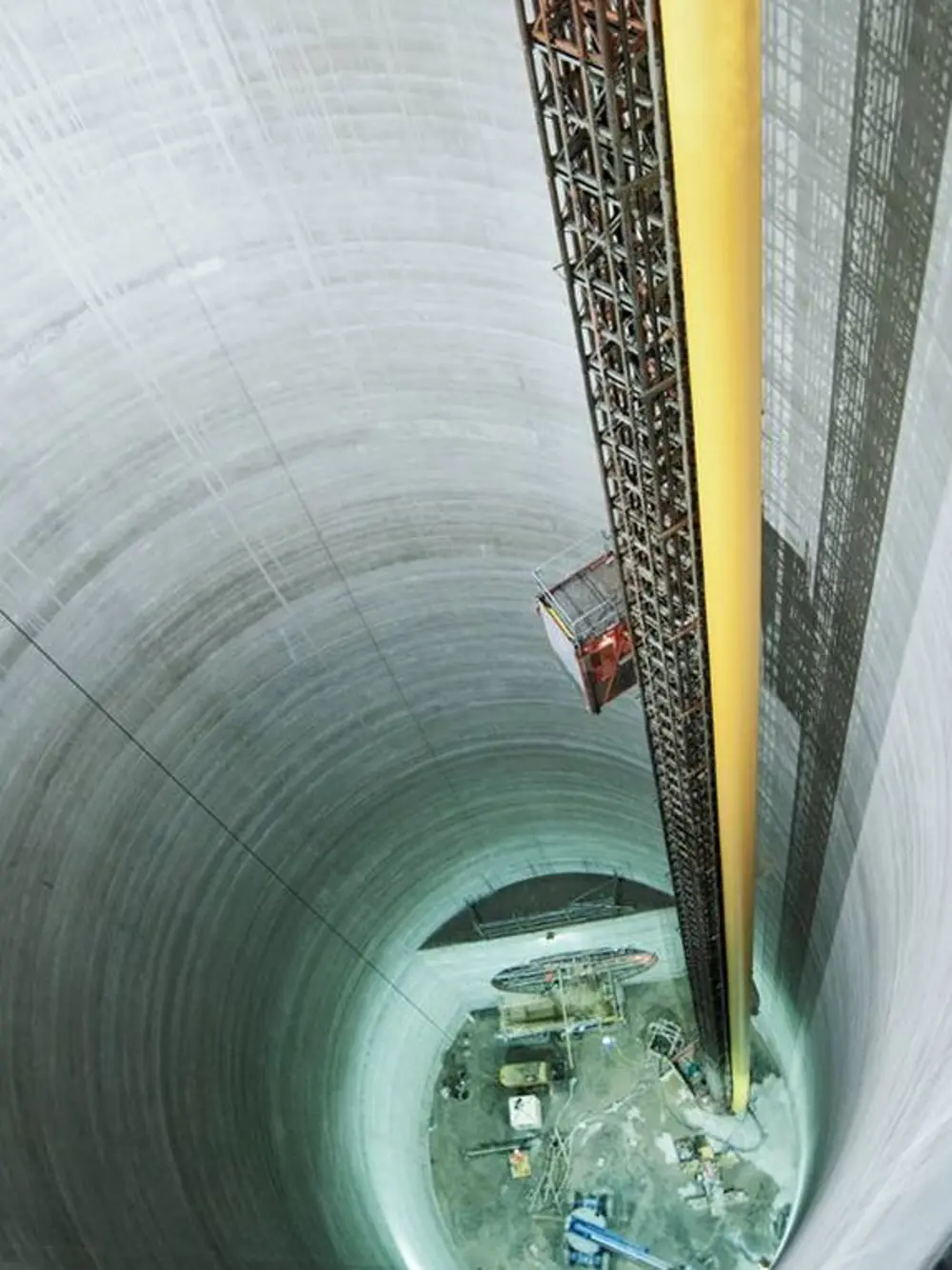
The Lee Tunnel overflow shaft shortly after construction of the shaft secondary lining and before the launch of the TBM. The excavation of this shaft was 79m deep and the diaphragm walls supporting this 20m internal diameter shaft (the smallest on the project) are 90m in depth. © Thames Water
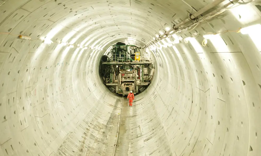
London’s deepest tunnel is now nearing completion in east London. When it is finished, the Lee Tunnel, with a total cost of £635 million, will stop the pollution of the nearby River Lee, which currently has to accept sewage and storm water beyond the capacity of the capital’s 19th century sewage system.
The Lee Tunnel is the first of two tunnels in Thames Water’s London Tideway Improvement Programme. The 6.9 kilometre-long tunnel forms the eastern, downstream end of the system. The Lee Tunnel will store and carry sewage and storm water from Abbey Mills pumping station in East London to Beckton Sewage Treatment Works.
Constructing the tunnel posed unprecedented challenges in dealing with high groundwater pressures. Its deepest sections run over 75m below ground level, where the groundwater pressure is up to 8 bar. But the greatest innovations came in construction of the five shafts, the largest ever sunk in the capital.
They involved the UK’s deepest diaphragm walls, and a world first in building the inner linings as huge stand-alone, concrete chimneys.
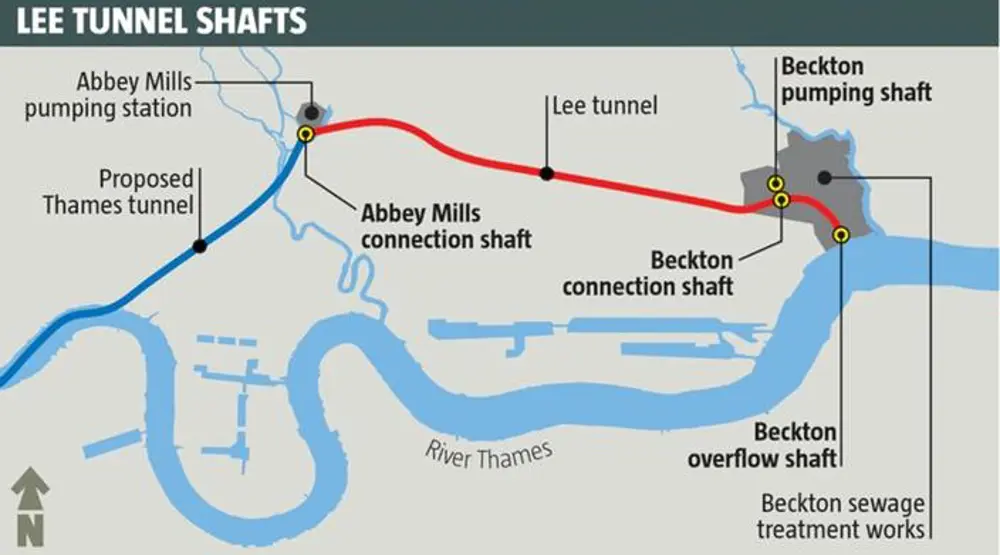
The 9.9 km-long Lee Tunnel runs from Joseph Bazalgette’s Abbey Mills pumping station in East London to Europe’s largest sewage works at Beckton, beside the River Thames. Later, it will connect to the larger Thames tunnel from West London © NCE
London's sewage system
In the 1850s, some 400,000 tonnes of sewage were flushed into the River Thames each day. During the unusually hot summer of 1858, the ‘Great Stink’ in the river was so overwhelming that it affected the work of the House of Commons. That same year, Parliament passed an enabling Act for the Metropolitan Water Board’s main drainage scheme, devised by Joseph Bazalgette, the Board’s engineer. Bazalgette’s system comprised 2,100km of sewers feeding into 131km of large interceptor sewers running west to east, parallel to the river. The system carried a mixture of sewage and storm water to discharge into the Thames downstream of the capital, and later, into sewage works. The interceptor sewers north of the Thames converge on the Victorian Gothic Abbey Mills pumping station, where the sewage is lifted to flow in huge brick pipes above ground along the Northern Outfall Sewer to Beckton, beside the Thames. By Bazalgette’s own estimate, the scheme saved around 12,000 deaths a year from cholera and other waterborne diseases.
Bazalgette anticipated the growth of the metropolis and designed his system to last, with the highest quality of construction and considerable spare capacity. To cope with occasional extreme events, such as major storm surges, he included 57 combined sewer overflows (CSOs), allowing the excess to overspill back into the Thames to avoid flooding.
The system has coped remarkably well for a century and a half, but Bazalgette’s ‘extreme events’ now happen about once a week. Every year, some 39 million tonnes of sewage mixed with rainwater flow through the CSOs into the Thames. About 40% of this discharge is from Abbey Mills CSO, from where it flows into the Thames via the River Lee.
Thames Water’s proposed Thames Tideway Improvement programme is designed to minimise these overflows, as well as improving the sewage works. The first stage will upgrade all sewage treatment works, the second is the construction of the Lee tunnel and the third will be the Thames Tideway Tunnel. The Thames Tideway Tunnel will run 25 kilometres from Acton in West London, directly below the Thames before veering northeast to Abbey Mills. From Abbey Mills it will connect into the Lee Tunnel to take the sewage to Beckton Sewage Treatment Works. The tunnel is deep throughout, to avoid the myriad existing services under London, particularly the cable tunnels under the Olympic Park. The sewage flows by gravity, so it is deepest at the eastern end, which is the Lee Tunnel.
Building the shafts
Sinking the shafts – two at Abbey Mills and three at Beckton, with the largest at 38m internal diameter with walls 98m deep – presented both a challenge and an opportunity. The project was challenging because of the depth, the groundwater pressures, and the tight tolerances on verticality. These ruled out conventional shaft construction techniques such as caisson sinking, or piling and underpinning with shotcrete (sprayed wet-mix concrete). It was also an opportunity, because more shafts will be needed further upstream, most of them much closer to existing buildings: the Lee Tunnel shafts could be a test-bed for developing safe and economical solutions.
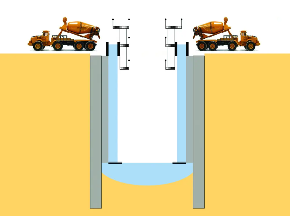
The first decision was to use traditional diaphragm walling techniques to create the outer linings of the shafts. The construction process exploits the extraordinary thixotropic properties of bentonite slurry: the slurry is semi-solid when static and can therefore support the sides of a trench, but returns to its liquid state when agitated. Trenches are excavated under the slurry, with cages of reinforcing steel lowered in, and then tremied (underwater) concrete is pumped to the bottom, displacing the bentonite as it rose. The technology, borrowed from the mining industry, was first introduced into construction in the 1950s – see Deepest-ever diaphragm walls.
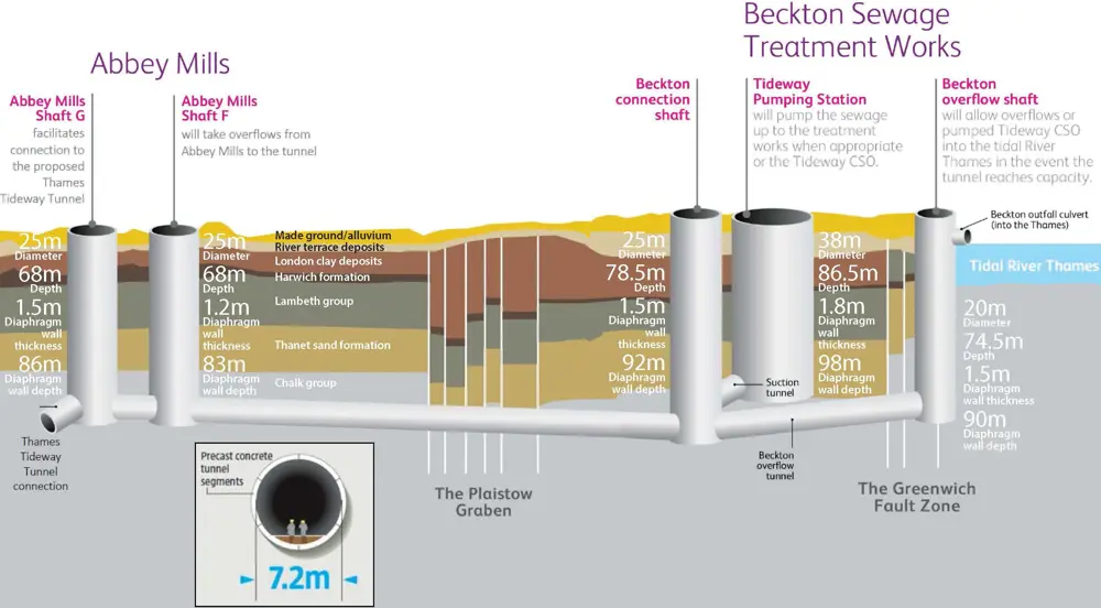
The five shafts for the Lee Tunnel, the largest ever sunk in London. The largest, at 38 m in diameter and with walls 98 m deep, will house the Tideway pumping station at Beckton. The tunnel was driven from the Beckton overflow shaft through some heavily faulted ground, particularly in the Plaistow graben © Thames Water
With the walls complete, the soil inside could be excavated, with internal relief wells to relieve hydrostatic pressure and avoid a 'blow-out' of groundwater before the base was capped. The massive, heavily reinforced base slabs, inverted domes, transferred the forces from the upward water pressure into the walls. The largest of these was 4m thick, with 4000 m3 of heavily reinforced concrete: another record for the Lee Tunnel.
Construction took 48 hours, pouring up to 150 m3 of concrete per hour.
Deepest-ever diaphragm walls
🚧 Overcoming the challenges in constructing the deepest ever tunnel shaft in the UK
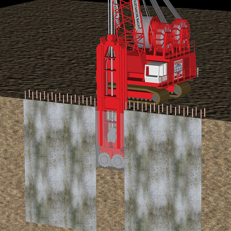
The Lee Tunnel shaft was to be the deepest ever sunk in the UK and presented several challenges. In particular, how could verticality be maintained within 1:300 tolerance over the full depth of nearly 100 m, and how could the resulting structure be as near as possible to a regular cylindrical shell? With the shafts working in compression to support the ground, verticality was essential to ensure sufficient overlap between panels to bring down the compressive stress in the concrete to within design limits.
The key to controlling these variables was in carefully monitoring what was going on. A conventional crane-mounted grab dug the trench in the upper levels. At the lower levels, a special ‘hydrofraise’ took over: a crane-mounted drilling machine fitted with two cutter drums rotating in opposite directions to break up the soil within the bentonite. A pump just above the cutter drums sucks out the soil and brings it to the surface with the bentonite, where filters remove the soil and return the bentonite into the shaft.
The hydrofraise contains instrumentation that informs the operator of the plan position, inclination and twist of the cutter body. Hydraulic rams and pressure plates on the cutter body can be jacked against the side of the panels to change the inclination of the cutter heads and correct any errors in verticality. As an innovation on the Lee shafts, this was supplemented by lowering an ultrasonic echo sensor into the trench, and configuring the output to give three-dimensional imaging of the excavation. The data confirmed that the maximum out-of-plumb at the bottom of the five shafts was just 15 cm – well within the required tolerance for these 38-metre-diameter shafts.
The shaft walls were sunk as a series of panels, 7.2 m long and up to 1.8 m thick, with gaps between panels. Each panel took a week to build, with concrete poured continuously to avoid the formation of ‘cold joints’, where there could be cracking and water penetration. The concrete mix was designed so that it did not reach its minimum compressive strength until 56 days after pouring. This gave the team enough time to construct the secondary panels through the primary panel concrete before the full strength was reached. As the hydrofraise dug out the soil for these infill panels, it also bit into the soft concrete at the edges of the adjacent panels, ensuring a proper overlap between panels.
Extensive monitoring of the construction, including pioneering use of fibre-optic monitoring was undertaken by a team from the University of Cambridge, led by Professor Robert Mair FREng. The work focused on the ground movements, shaft movements, and stresses within the diaphragm walls during excavation. This provided useful data associated with the impact of such shafts on adjacent facilities as well as a better understanding of their structural behaviour. Very low movements were measured during shaft construction, orders of magnitude below empirical predictions, however bending moments were slightly higher than the design. The increase in bending movement is believed to be due to the walls being stiffer than the design and having a good concrete to concrete joint between panels.
Creating the shaft's inner lining
The smooth-faced inner lining, with its many cut-outs and details, still had to be added inside the main shaft. The initial proposed approach, simply pouring reinforced concrete against the diaphragm wall, would have created problems. As the concrete set and cooled, it would have shrunk and separated from the surrounding diaphragm wall. Groundwater pressure would cause the lining to creep further. Then, when the shaft was full, the pressure could force the lining into hoop tension, with a tendency to crack. This, in turn, could allow sewage to penetrate the concrete, corroding the steel reinforcement and reducing the life of the concrete.
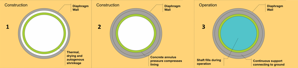
How the novel twin-lining design for the LeeTunnel shafts works:
(1) The standalone inner lining (green) is slip-formed within the diaphragm-wall outer-lining, leaving an annular gap between. As the concrete of the inner lining cools and dries, it contracts, increasing the width of the annulus slightly. (2) As the annulus is filled, the fluid pressure from the large head of unset concrete compresses the inner lining, before the filling itself sets. (3) When the shaft fills during operation, the pressure is reversed. Because the inner lining is already compressed, and has further support from the surrounding ground through the outer-lining and the annulus infill, it is prevented from going into tension and cracking images courtesy of Mott MacDonald
The Lee Tunnel shafts’ cylindrical outer lining was built using diaphragm walling techniques, anchored into the ground well below the shaft base which minimised the groundwater ingress into the excavation. Then the standalone unreinforced inner lining (pale blue) was slip formed from the bottom up, and the massive inverted-dome base cast. Finally, the gap between the two linings was filled with slow-setting grout, to pre-stress the inner lining images courtesy of Mott MacDonald
Furthermore, the Lee Tunnel project had adopted new Eurocodes that are particularly strict on crack widths for water-retaining structures: the inner lining could be built to resist this cracking, but only with massive reinforcement at huge cost and packed so densely that it would be difficult to compact the concrete around it.
The design and engineering team came up with a simple and ingenious solution. In a world first, it decided to build the inner lining inside the shafts as a 700-750 mm-thick standalone concrete cylinder. It decided to use slipform techniques to create the lining, with no reinforcing steel and with the lining separated from the diaphragm wall.
This would enable the annulus between the two linings to be filled with exceptionally slow-setting concrete, allowing enough time for a head of wet concrete to build up significant pressure at the bottom of the shaft to force the inner lining into compression, effectively locking the linings together and pre-compressing the inner lining to resist any later outward pressure from a full shaft. This would prevent any hoop tension which could crack the lining. The team’s decision would also save more than 3,500 tonnes of reinforcing steel, and shave about six weeks off the construction time for the largest shaft.
Translating the idea into reality was more challenging. The bottom of the cylinder had to be separated from the base slab so that it could move freely during setting and compression. The solution was to separate the two with a slip joint comprising two layers of 2mm-thick PVC slip membrane with grease in between. A low-heat concrete mix was designed, with steel fibres added to the mix both to increase ductility and to control shrinkage cracking. Full-scale beam tests convinced the team that the concrete would perform as required.
Then there was the question of organising the world’s largest-ever continuous slipform concrete pour – 11,350m³ over 28 days for the largest shaft – with little access to the outer face and complex details and box-outs to be included. All had to be planned in meticulous detail beforehand: an interruption to the slipform would not have been disastrous, but each delay would have cost an estimated £500,000. When it came to concreting in the annulus between the two linings, no interruptions could be contemplated. The design concept depended on maintaining a continuous concrete pour to provide a uniform pressure increase and avoid uneven vertical load distribution.
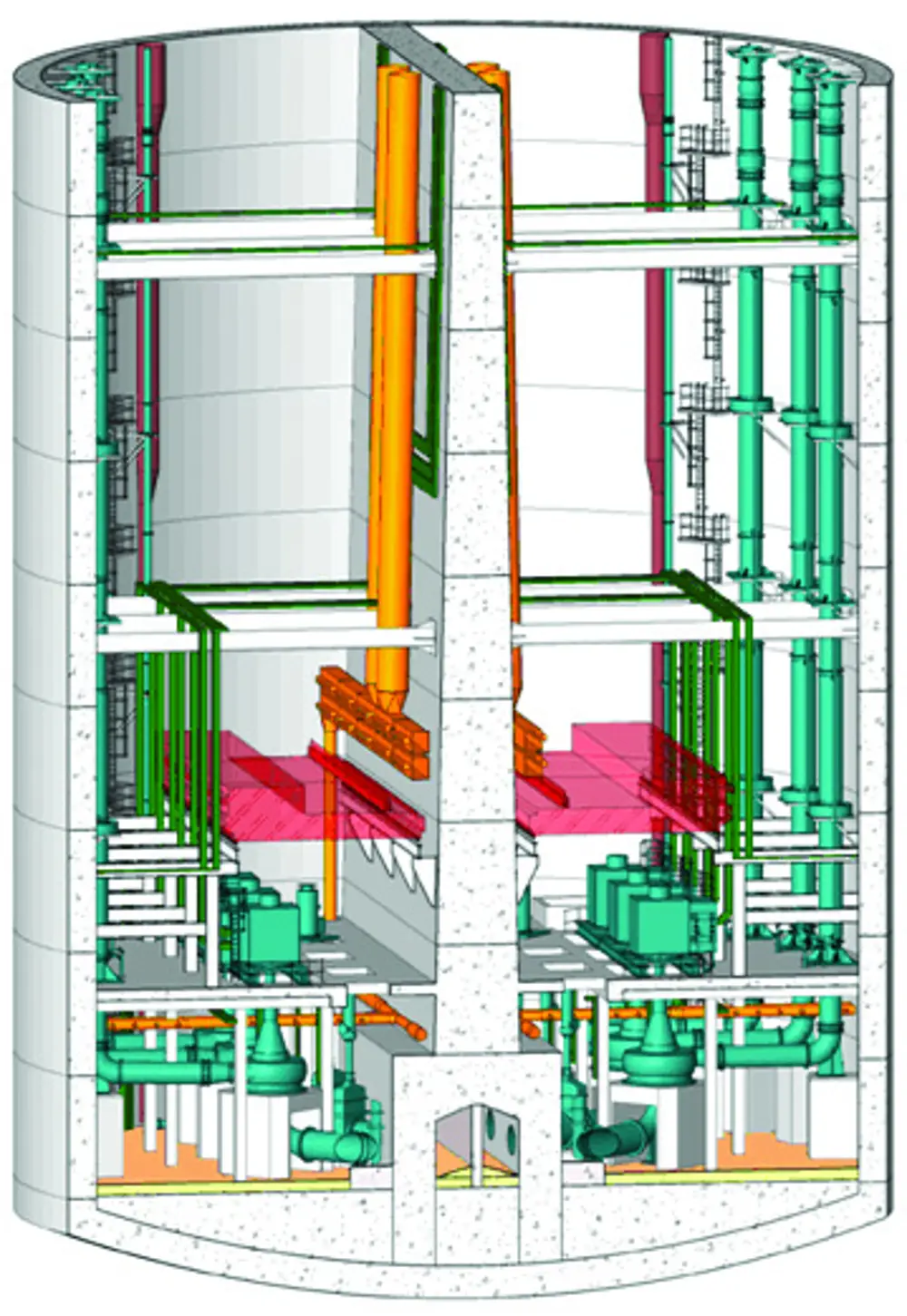
Six large pumps are being installed in the Thames Tideway pumping station, each with a capacity of 3.05 m3 per second. These will lift the flow to the surface and into a gravity-fed flow discharge system which runs into the sewage treatment works. The pumps are arranged either side of a culvert in the pumping station, which is fed via a suction tunnel from the connection shaft. The culvert supports a central full-height dividing wall in the pumping station, providing a robust system in the event of a catastrophic failure as one half of the station will always be operational © Thames Water
Deep tunnelling
With the work on the vertical shafts underway, the head of the tunnel boring machine (TBM) was lifted into one of the Beckton shafts. At over 800 tonnes, the TBM required the largest mobile crane in the country. The machine was then gradually assembled during construction of the tunnel to its full 120m length by 8.88m diameter to drive the tunnel through chalk to Abbey Mills. Use of TBMs has become commonplace in the UK, notably for the Channel Tunnel Rail Link and more recently for London’s Crossrail – see Ingenia 56. But once again, the Lee Tunnel is setting records. This was to be London's deepest ever tunnel, and the deepest use of a TBM anywhere in the UK, with groundwater pressures up to 8 bar.
For this reason, the project team chose a slurry pressure balance system for the machine. This used a sealed clutterhead chamber, pressurized with chalk slurry that supported both the ground and the groundwater pressure during tunneling. With the pressurized chamber confined to the front face of the TBM, the miners were able to work behind the chamber at normal atmospheric pressure. The mixture of slurry and excavated material was pumped back to the surface where a succession of processes including a rotating screen, centrifugal separation, vibrating screens and filter presses, separated the soil. The slurry was recycled and returned to the TBM with the semi-soiled spoil shipped down the Thames to cap landfill sites in Kent and Essex. Lee Tunnel Planning Conditions dictated that all spoil material from the tunnel and shafts should be removed by river rather than road, which saved 80,000 on lorry movements. The primary lining of the tunnel consists of 350mm-thick precast segments of fibre-reinforced concrete, installed as the TBM progresses. To minimise the chance of leakage through the lining, the segments were precast to tight tolerances of a fractions of a millimetre and the segments and molds were checked by a state-of-the-art laser checking system. In another UK first, a flexible gasket made from ethylene propylene diene monomer (EPDM) was cast into the sides of each segment, rather than being glued into a chase, which again gave great quality benefits.
One of the biggest concerns was having to open up the face of the machine for manual intervention, for emergencies or for routine maintenance. Working at such deep levels would have required miners to have long decompression periods at the end of each shift, and with pressures higher than 3.5 bar, the tunnelers would have had to resort to deep-sea diving technology. The machine was also tunnelling through chalk that contained highly abrasive flint nodules and sheets that would cause heavy wear to the cutterhead tools and to the slurry system pipework, requiring them to be changed several times during the dive.
In addition, the tunnel had to pass through fault zones and areas of bad ground where the ground would not be self-supporting in the face under the 8-bar groundwater pressure. By closely monitoring both ground conditions and cutterhead wear, the contractor carried out all maintenance in short, planned interventions. These took place in areas where the ground was good chalk with limited fissuring, where both pumps and the workforce would cope with the inevitable ingress of water without having to work under compressed air.
In addition, the tunnel had to pass through fault zones and areas of bad ground where the ground would not be self-supporting in the face under the 8-bar groundwater pressure
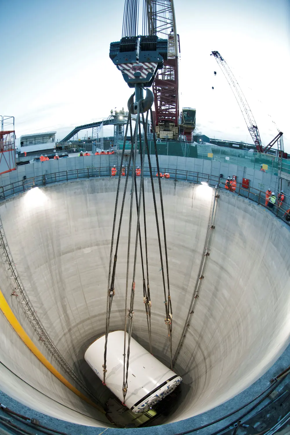
Lowering the 800-tonne Tunnel Boring Machine cutter head down the Beckton overflow shaft © Thames Water
Design of the inner tunnel secondary lining presented similar challenges to the shafts. It had to resist the high differential pressures without the concrete cracking, and without having to use large amounts of steel to reinforce the concrete. Unlike the vertical shafts, there was no simple way of effectively pre-compressing the inner lining, so the team concentrated on the design of the fibre-reinforced concrete. It opted for Dramix 5D fibres, new on the market and made in Belgium from high-ductility wire with an ultra-high tensile strength and shaped to provide additional anchorage into the concrete at both ends of the fibre. Large-scale beam test confirmed that, under tensile strain, the concrete showed good ductility, with good post-cracking performance and an equal distribution of cracks along a given length. The solution saved thousands of tonnes of reinforcing steel, as well as saving time.
Starting in May 2014, concrete was pumped down the shaft at Beckton, transported by rail cars and placed in giant 30m-long hydraulic shutters to create the 300mm-thick, 7.2m internal diameter lining. As construction neared completion, te project switched attention to the immense mechanical, electrical, instrumentation control and automation packages required to ensure that London's new sewage and floodwater system operates correctly when put into commission.
The design innovations for the shaft linings have not only yielded a significant commercial saving on steel, but by largely removing the need to handle and fix heavy reinforcement, they have enabled faster, safer construction. Minimising the steel content and carbon footprint significantly will also improve durability over the lifetime of the Lee Tunnel. The major concerns of steel corrosion and spalling common to all reinforced concrete water-retaining structures, especially those subjected to the aggressive compounds found in sewage, will have been much reduced.
Lee Tunnel main parties
📚 Who were the people involved in the Lee Tunnel project?
CH2M Hill – Project managed and led Thames Water’s Project Management Team
AECOM – Reference designed and gave technical support to CH2M Hill
MVB – Morgan Sindall - Vinci Construction Grands Projets - Bachy Soletanche Joint Venture.
UnPS – Underground Professional Services, the detailed design of the tunnel linings, the pumping station shaft, Shaft G inner linings, internal structures and ancillary culverts
Mott MacDonald – The detailed design of the overflow shaft, connection shaft and Shaft F internals and secondary linings, the design of the flow transfer scheme, MEICA design
Bachy Soletanche – The detailed design of the diaphragm walls and piles
Coming online
It is 150 years since Bazalgette’s first intercepting London sewers were completed in 1865. When it opens later this year, the Lee Tunnel will prevent 16 million tonnes of stormwater and sewage being discharged into the Lee River from the Abbey Mills combined sewer overflows each year. At a cost of £190 million, Thames Water is expanding the Beckton Sewage Treatment Works, already the UK’s largest, by 60% to cope with the discharge from the Lee Tunnel.
The government has now given planning consent for the remainder of the 25-km tunnel to be built, and the project has named preferred bidders for its construction packages. Subject to outstanding objections and conclusion of the funding arrangements, work should start next year, with tunnel construction following in 2017. The Thames Tideway project is scheduled for completion in 2023.
***
The author would like to thank engineer and freelance writer Hugh Ferguson for his help in compiling this article. Ferguson interviewed Chebli Matta, design and engineering manager for MVB.
This article has been adapted from "London's deepest tunnels and shafts", which originally appeared in the print edition of Ingenia 63 (June 2015).
Contributors
Richard Sutherden is the client side design manager on the Lee Tunnel Project and is technical director, tunnels and underground structures, with the global integrated infrastructure services company AECOM which prepared the initial design and now supports the project management team led by CH2M Hill.
Get a free monthly dose of engineering innovation in your inbox
SubscribeRelated content
Civil & structural

Building the Shard
The Shard is one of London's most iconic buildings. The tallest in Western Europe, it was designed by Italian architect Renzo Piano and dominates the city’s skyline. Ingenia spoke to John Parker, project director for structural engineers WSP, who outlined the engineering decisions made in building the enormous steel and glass structure.
The return of arched bridges
Arch bridges are strong, durable and require little maintenance. However, very few had been built since the early 1900s until the FlexiArch was developed and launched in 2007. Now, there has been a minor renaissance for this ancient form of construction.

Creating user-friendly buildings
For Michelle McDowell, a former Business Woman of the Year, a passion for joined-up design thinking and building information modelling with a user-friendly approach has enabled her to pioneer revolutionary changes in her field.

Troja Bridge
In November 2014, one of the world’s largest network arch bridges was officially opened in Prague. The UK may soon have its first network arch bridge if the go-ahead is given for a new rail project in Manchester.
Other content from Ingenia
Quick read

- Environment & sustainability
- Opinion
A young engineer’s perspective on the good, the bad and the ugly of COP27
- Environment & sustainability
- Issue 95
How do we pay for net zero technologies?
Quick read
- Transport
- Mechanical
- How I got here
Electrifying trains and STEMAZING outreach

- Civil & structural
- Environment & sustainability
- Issue 95